A new dad finder for the new home.
A new dad finder for the new home.
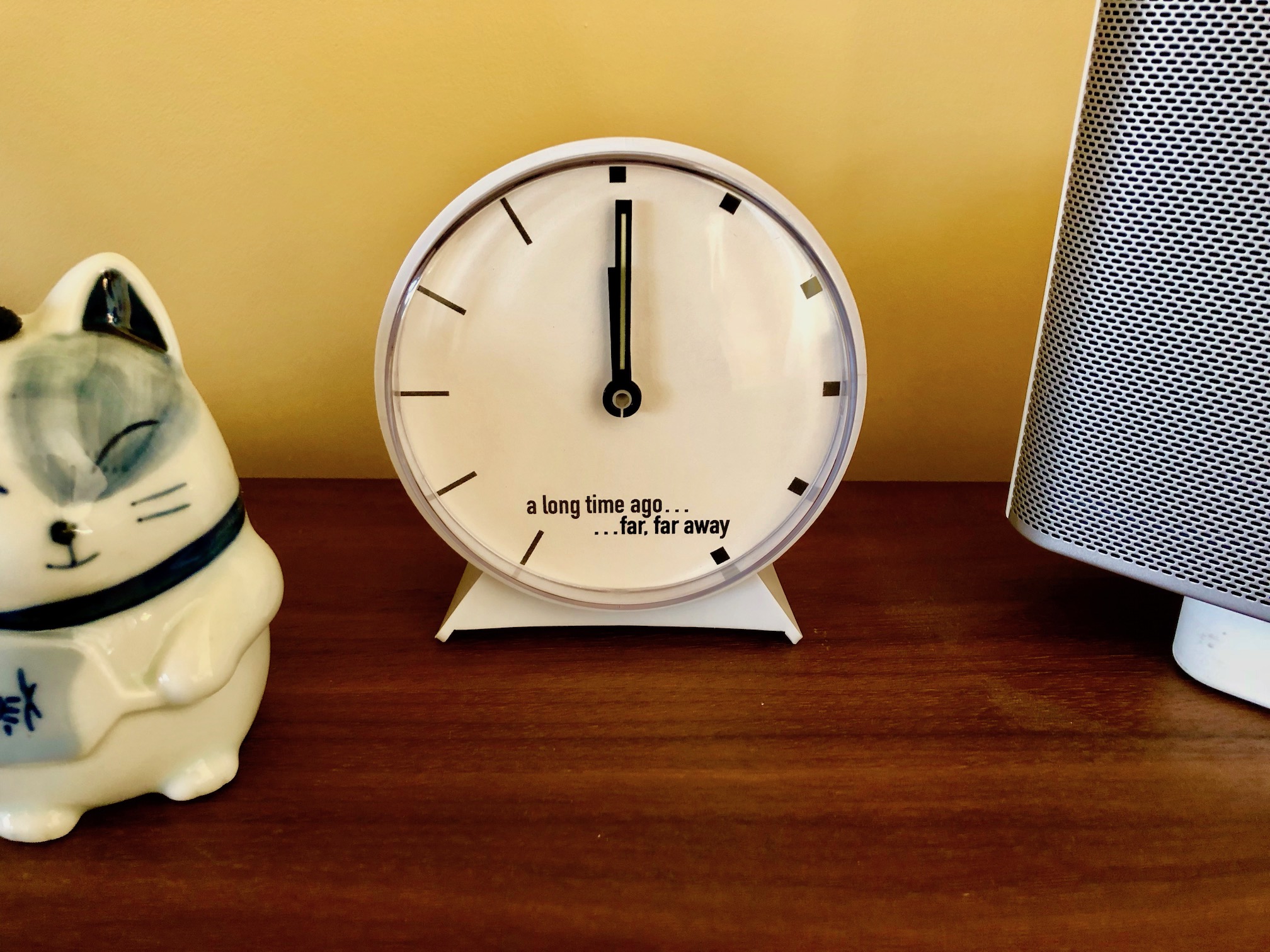
Three years after making my Dad Finder, I needed to update it to reflect my new commute. Rather than just print a new face for the clock, I decided to make a new version of Dad Finder with a new form factor and updated hardware.
I had picked up a frame from Ikea that is deep enough to conceal some hardware. I originally planned to use it to embed a few LED matrixes behind some artwork to display messages, but decided to use to mark my location on a Cold War era Soviet made map of the Bay Area.
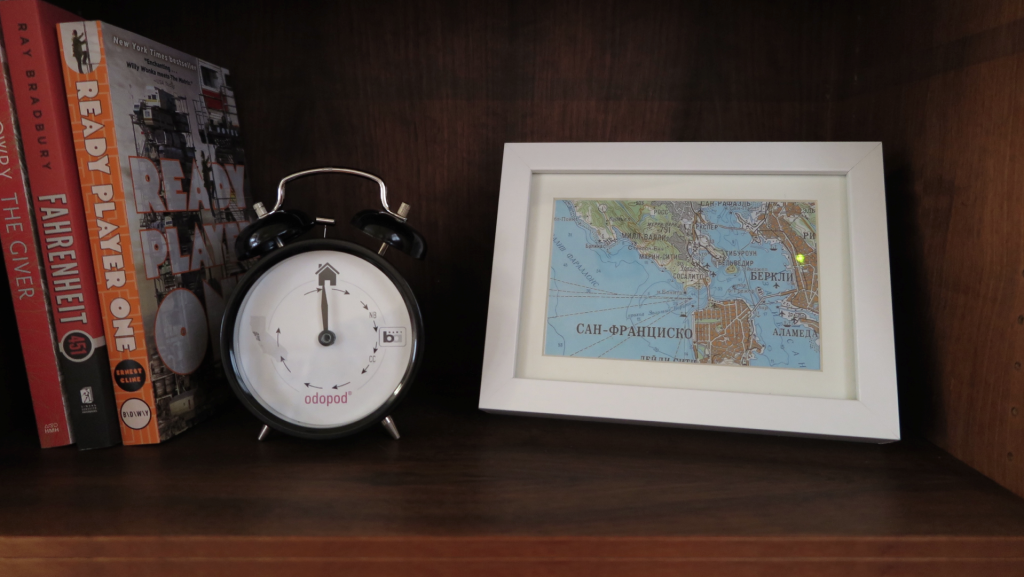
Dad Finder v1(left) and v2(right)
For the hardware, I chose the Particle Photon which connects with the Paticle.io cloud platform. This was a radical simplification over the first Dad Finder which used five different components to connect to the internet and expose and API for me to hit from my mobile app. Additionally, the Particle platform has the advantage of being supported by IFTTT, so I no longer needed to use my own custom app to trigger updates as I move through different geofences.
Behind the map is a series of bi-color LEDs, one per location that I want to display on the map. On entering a geofence, I light the LED green, on exiting a geofence, I light the LED red.
The code for the Photon is available on GitHub.
After using the new map for a few days, I received some complaints that it no longer made any sound. In the first version, the clock’s hand is moved by a hobby servo that makes a signature sound when moving the hand to a new position. The LEDs updated soundlessly and it turns out that my family missed having the audio cue that let them know that I was on the move.
To remedy the situation I added a small piezo speaker to the picture frame and added the ability to play melodies as the different zones are activated. We decided that some snippets from classic video games would do the trick. At present it plays the Mario 1-up sound when it starts up and either the first 4 notes or all 12 notes from the Zelda found item tune. Expanding the set of melodies so that each geofence has its own sound is on the todo list.
I really enjoyed working with the Particle Photon hardware. The whole platform is quite easy to use and it is nice not to have to think about connectivity at all. To pass messages between IFTTT and my Dad Finder, I subscribe two functions in my Photon code (lines 9 and 10 in the source code). To trigger the function, I set up a series of recipes in IFTTT each defines a geofence and publishes to either the updateExisting or updateEntering event with Data that identifies the correct LED to light within the data of the event.
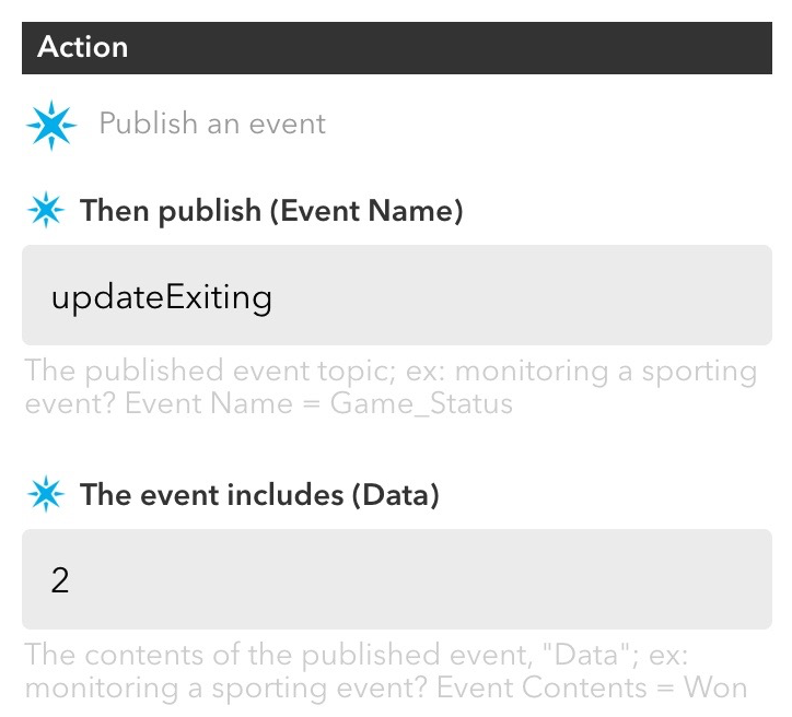
Screen capture of example recipe from IFTTT
These events automatically trigger the assigned functions within the Photon code (lines 33 and 40 of the source code).
This is radically more simple than working with the Xbee radio which required coding and configuring many more pieces including the Arduino board, the radio module, the hub, the Digi cloud service and an App Engine app to trigger the events reported from my mobile app. What took many weekends to set up on version 1 of Dad Finder took only a couple hours for version 2.

The components used to connect v1 (top) and v2 (bottom)
However, it did take a bit of time and trial and error to get things stable on the Photon. Originally I was trying to use an LED matrix and backpack from Adafruit, but using that in combination with the cloud platform seemed too much for the Photon. I found myself restarting the board often to reestablish connectivity with the cloud. Even after simplifying the code to its present state, I have had to update the firmware to improve reliability.
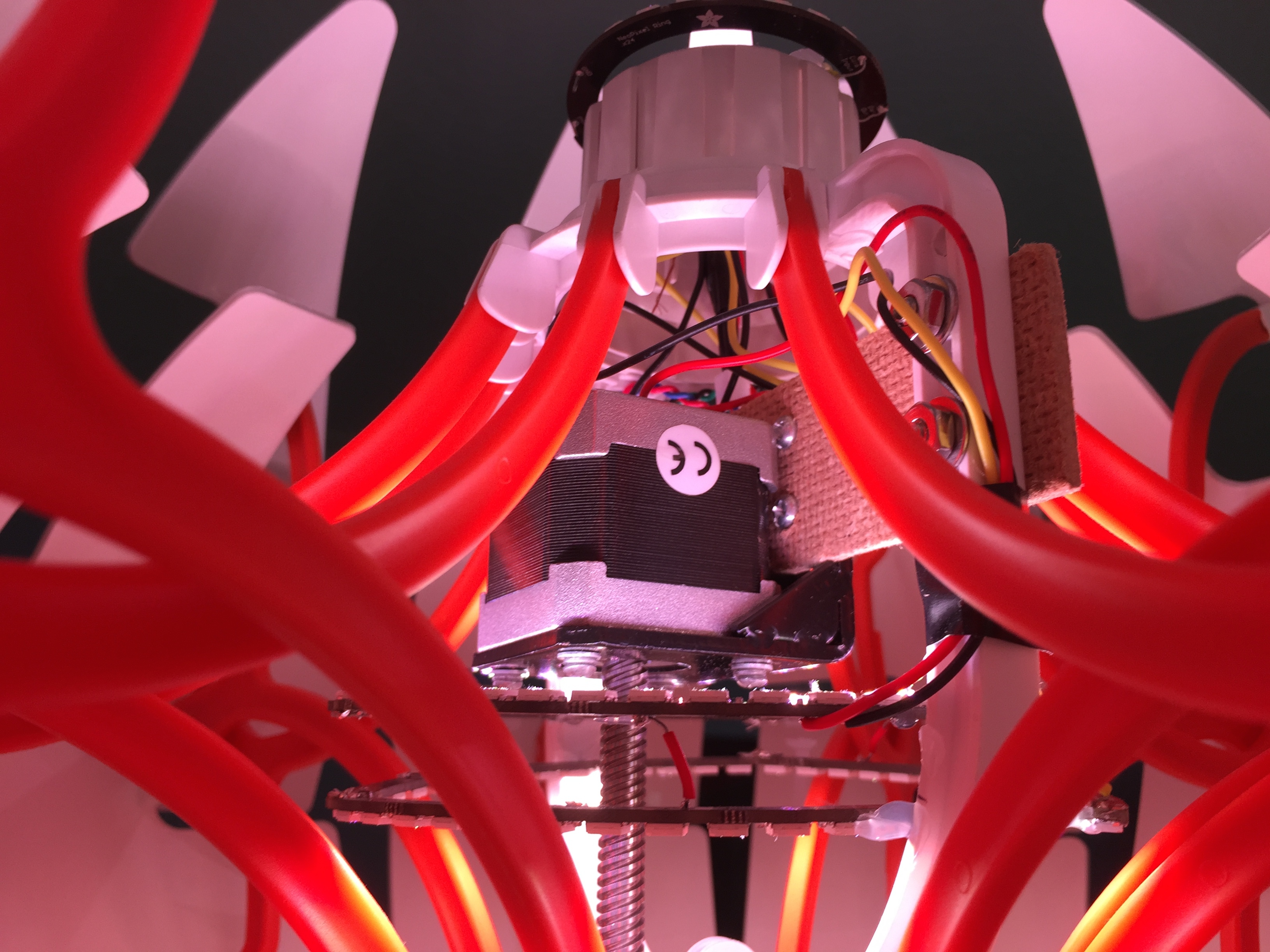
The Death Star inspired IKEA PS 2014 Pendant Lamp is a great platform for a connected home hack. Mine is shown in the video below.
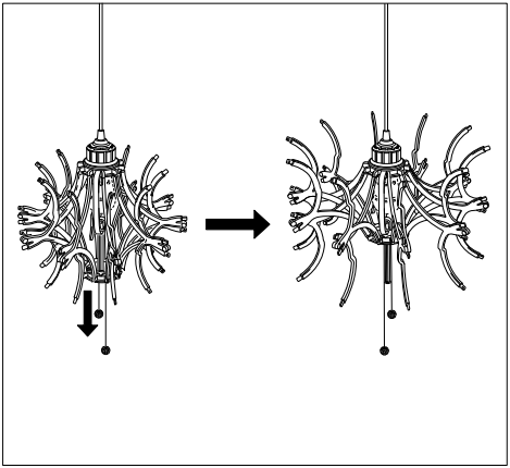
Out of the box, the lamp uses a string and pulley system to open and close the spherical shell. It is a relatively simple mechanism where two strings pull a platform up and down a central spine. Ten scissoring arms attach to this moving platform and to a fixed platform near the top of the lamp. Moving the bottom platform up the spine spreads the outer ends of the arms, opening the lamp’s outer shell (see diagram below from the lamp’s assembly manual).
There is a void where the lightbulb normally sits between the top-most position of the moving platform and the upper platform. This provides the space for the stepper motor and LEDs needed for my modifications. The upper portion of the spine which splits in two to accommodates this space also offers a convenient platform to attach these new bits to.
Lastly, there is cap used to cover the wiring where the lamp anchors to the ceiling. This provides a convenient space for electronics. In my case, I’m using an Arduino Uno, an Arduino Motor Shield and a SmartThings Shield.
I replaced the standard wiring with a Cat5 ethernet cable to connect my electronics in that cap to the motor and LEDs in the body of the lamp. Four of the Cat5 wires are used to control the motor and three for the LEDs, leaving one unused wire.
Given the design of the lamp, it seemed easier to directly drive the lamp’s lower platform rather than try to pull the strings that the lamp ships with. I first thought I would attach a threaded rod to a standard stepper motor, but then I found this motor with a lead screw that is long enough to cover the entire length of the lamp’s spine.
I attached the motor using a standard mounting plate and a fiberboard bridge attached to the central spine of the lamp.
Driving the motor was simple once I found a motor shield that could power it. I first tried Adafruit’s Motor Shield, but it does not provide enough power. After realizing this, I did a bit more research and determined that the Arduino Motor Shield should be able to drive the motor. And it is.
The video above shows the motor moving the platform and opening two of the ten arms. When the lamp was finally assembled, I cut off the last few inches of the screw so that it was just a little longer than the spine.
For the lights, I wanted the flexibility to individually control an array of RGB LEDs. I’ve used the NeoPixel rings before in another project and really like how simple they are to use and how the ring format provides very nice visual effects with relatively simple animations.
Given the design of the lamp and the need to work around the motor’s position, I wanted to use the larger 60 LED ring configuration. Unfortunately, the rings could not fit in any one location when the lamp’s arms were both extended and contracted. Luckily, each 60 LED rings is actually made of four 1/4 circle arcs. I ended up using two sets of three arcs in triangular configurations (one triangle facing down and one facing up).
I then added a 24 LED ring to the top of the lamp to add a bit more brightness. This also works to fill some of the shadows cast on the ceiling by the internal LEDs. The results are great, especially when the lights are animating.
I’m using the SmartThings platform to control the lamp. I went this route for two reasons: it is relatively easy to build a controller UI to use within the SmartThings app and I can integrate it with other things in my house connected to the SmartThings platform.
I created the UI by writing a device handler. The handler sends commands as strings to the SmartThings Shield which are then passed as a parameter to a designated handler function running on the Arduino.
I have not yet connected the lamp to other things but this can be done by writing a SmartThings app.
Very early on in the project, it was clear that constrained RAM on the Uno would be an issue. The first indication was that the board kept restarting with all three components integrated (while any two components worked well).
The first step was to do some simple optimizations to the types of variables I use (e.g. uint8_t in place of int). With this I was able to could get the three components working together; however, memory was still maxing out when I sent long strings from SmartThings. “SetColor: 255,255,0” would work but, “SetColor: 255,255,255” would cause problems. Simply shortening these to “sc:255,255,255” did the trick.
Then something quite surprising happened. The .toInt() function that I use to convert the strings to integers would periodically stop working and convert any three color values to 0,0,0 until I restarted the Arduino board.
I tracked this down to what I believe to be another memory issue, but one more complicated than simply running out of memory. Removing the motor code from the project (and freeing a good deal of memory) was not fixing the issue. On the other hand, removing some of the strings from the sketch that were used to parse the commands sent from SmartThings (freeing up very little memory) did fix this new problem.
In the end, the fix was to further shorten all command strings and to reduce the overall number of commands by consolidating related commands into individual commands with enums.
The lamp can be turned on and off from a standard wall switch so it was important to me that I persist some of the settings while the power was off.
Retaining the position of the moving platform is most important since doing so frees me from adding sensors to know when the lamp is fully open or closed (and thus keep the motor from grinding away once it reaches one extreme or the other).
I also save the NeoPixel RGB and brightness values.
I originally planned to use an FRAM memory module but my previously mentioned memory constraints as well as some pin constraints imposed by the motor shield forced me to reconsider. I decided instead to take a shortcut and use the Arduino’s built in EEPROM memory. This is volatile memory rated for 100,000+ writes, but I’m ok with that trade-off for now.
During development I powered the motor and lights through the Arduino with the lights hooked up to VIN. This worked fine as long as I dimmed the LEDs before running the motor.
However, when run at any significant brightness for moderate periods of time, the power would cut off. This is because the 114 NeoPixels pull about 3 amps at full brightness and my 2 amp power source shuts itself off before damage is done (there is a thermal switch that is thrown as it overheats). Using the recommended calculations it was clear that I should be using a dedicated power supply rated for at least 7 amps.
In the final installation, the lamp is powered by two 5V supplies. The first is a 2 amp supply used for the Arduino and motor plugged into the Arduino’s barrel jack. The second supply is a 10 amp supply connected to the LEDs using this barrel jack adapter (with the ground tied to both the LEDs and the Arduino).
All in all, this was a fun project and I’m pleased with the the results. It presented a number of puzzling challenges both with modifying the physical lamp and getting the different electronics working together and I learned a number of new details along the way.
You can find the Arduino and SmartThings code on GitHub.
If you have any questions let me know in the comments and I’ll do what I can to answer them. And, if this you build your own, I’d love to see it.
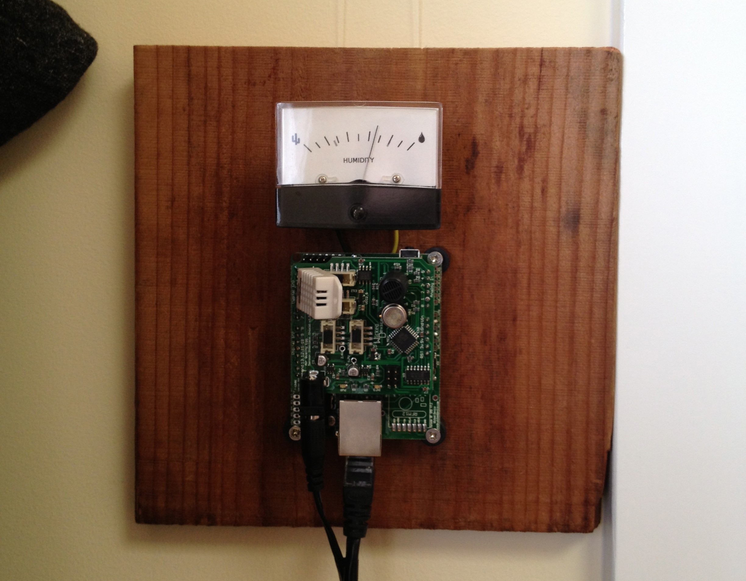 I was not thrilled with the air quality egg enclosure that shipped with the final product and since I planned to use it inside, I decided to mount it on a plank of wood and leave the circuitry exposed. I also wanted some sort of display so I added a meter and modified the code to use pin 3 (pwm) to display the humidity.
Original project date: April, 2013.
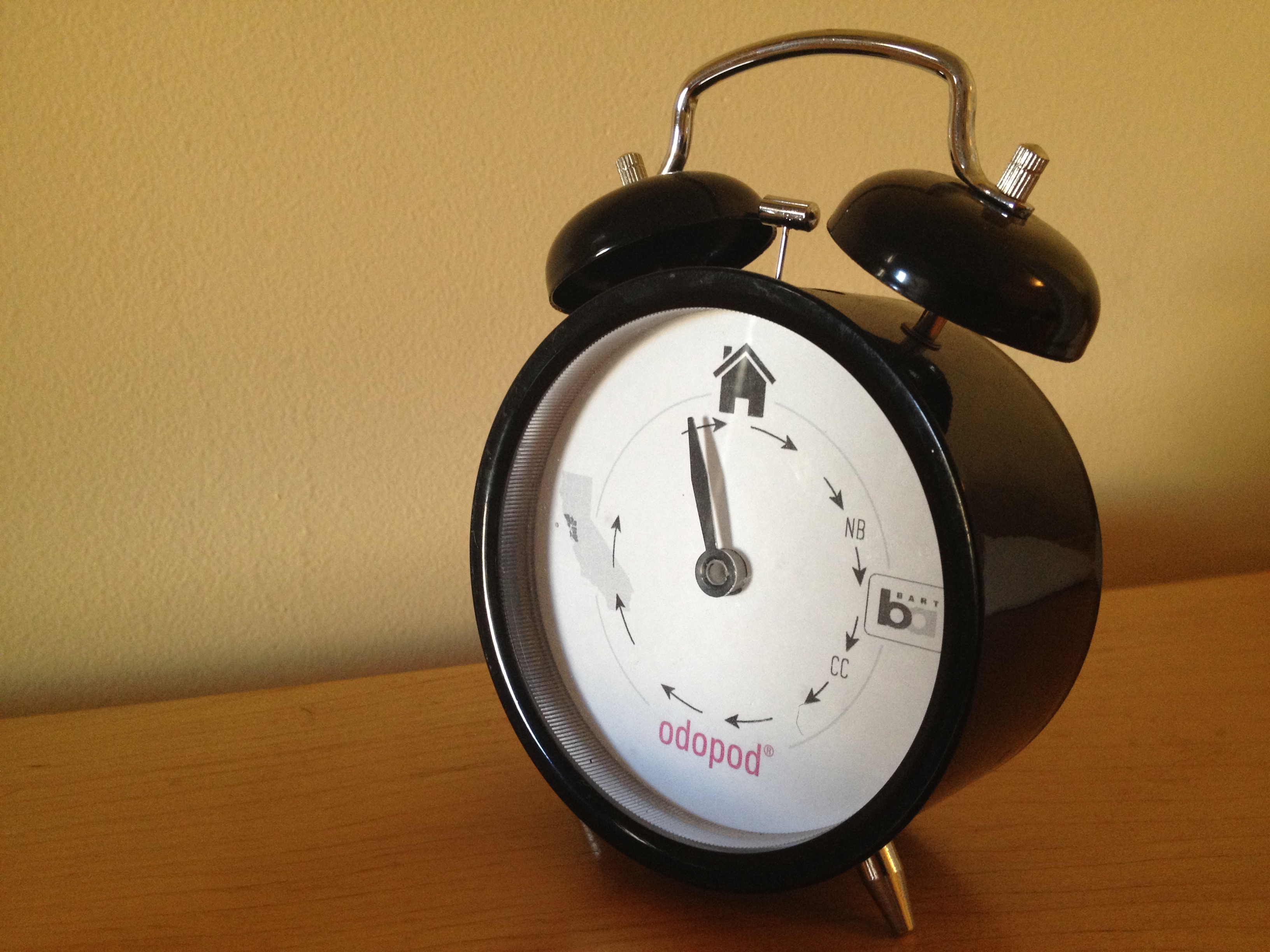
This Ikea clock was modified to display my location for my family at home. It is nice that they can check up on me without checking online. The kids are especially enjoying it.
I use 5 different geofences in an iOS app, monitoring entrances and exits for key points on my daily commute (and the bay area as a whole). The app reports the triggers to a Google App Engine app. The minimal time allowed by iOS is enough to get the call through to the server. GAE then passes the events onto the clock via the iDigi web service.
Inside the clock, I use a Fio and Xbee radio paired to my ConnectPort x2. iDigi is able to push messages through the ConnectPort to the Xbee and update my status.
Original project date: Dec, 2012.

Last week, Guthrie Dolin and I presented at the Planning-ness 2012 conference. The conference was great, and I love it’s theme, “Get Excited and Make Things.”
The standard format for a session is present on a topic and then run a workshop in which conference participants make something to present back to the group.
In our session we provide an overview of the Internet of Things before going into detail about the potential of connected objects to encourage specific behaviors. We break down the components of an IoT ecosystem and discuss how they can be used to collect data and drive insights and change.
Following the presentation, the assignment was to use the framework and design a physical product and service around a personal object or situation. We provided a few catalysts and blank worksheets to help get people going. The results were great and we’ve posted each group’s worksheets on slideshare as well.
All-in-all, a great expreience and a ton of fun. Thanks to everyone who turned out to learn about the Internet of Things.