penelope: a vertical pen plotter

For a while now, I’ve wanted to draw some of my line drawings onto large format paper and I’ve finally built myself a vertical plotter. There are several great tutorials online for building plotters that suspend a drawing gondola from two motors, use polar coordinates to control how the gondola travels, and a servo motor to raise and lower the pen. The video below shows a complete test plot on my plotter.

Design

Much of the inspiration for the design of the penelope’s gondola, came from MTvplot. Like MTvplot, I decided to use large bearings with attached arms that rotate around a central point where the pen is placed. Keeping the pen tip in the center like this increases the accuracy of the plot. As the gondola moves left to right, the body of the gondola tends to rotate a bit relative to the the paper (for example, due to cable drag). With the tip at the center of rotation, the tip remains in the same place as the body rotates. Below are images of the first version of my gondola which is missing the weight I added in a later version.

To be able to easily adjust the width of my the plot area, I designed the motor mounts to hang from some picture rails already in my space. Within these mounts, I included smaller bearings to apply pressure to the belt and help hold it in contact with the teeth of the pulleys. I saw a similar detail in one of the online examples, but I can’t find the reference again.

For the counterweights, I settled on using pennies and printed cylinders to hold them. One of the benefits of this approach is that I was able to easily tune the weight by adding and removing pennies. At first, I tried to weigh the gondola only using the bearings (v1 pictured earlier), but I found that they did not provide enough stabilization when the distance between the gondola and motors was greater (for example, the bottom third of my 18×24 inch paper). This resulted in some shaky lines when drawing tight curves near the bottom of the page. To improve stability, I added a cylinder to hold pennies to v2 of gondola.

To help hold the pen with the tip at the center of the bearings and, when possible, at an angle to let ink flow down, I created a general purpose guide. This guide, is useful for quickly testing different pens, but proved difficult to set up accurately. I then created specific inserts to hold pens I plan to use regularly.

update: STL files available on Thingiverse.

Contoller

For the hardware needed to control the motors, I first started with these two tutorials: https://www.instructables.com/Vertical-Plotter/ and https://www.youtube.com/watch?v=T0jwdrgVBBc. I liked the simplicity of using the motor shield and Arduino Uno — plus I already had that hardware. In the end, I got it working, but the pen traveled too slow to be useful. A friend recommended PenPlotter which uses a board specifically designed for controlling 3d printers. With this hardware, the PenPlotter software and the Repetier firmware included in the PenPlotter repo, I was able to get penelope drawing well.
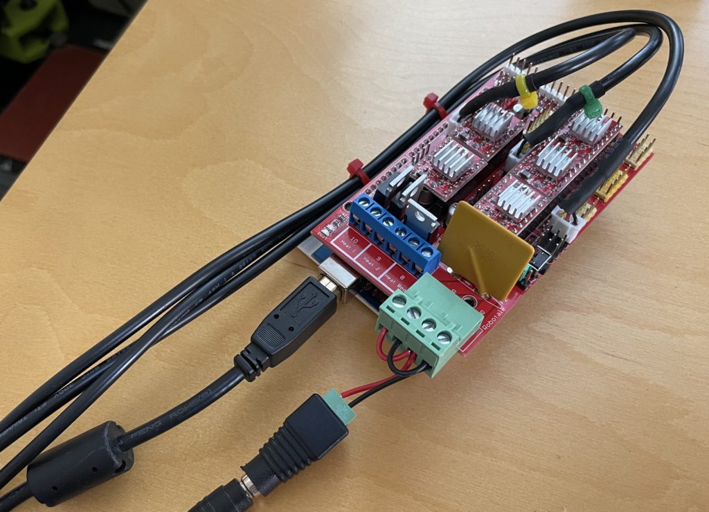
Hardware shopping list:

The PenPlotter software requires some plotter-specific settings. For my current installation, they are:

  • machine.motors.mmPerRev = 40. Calculated by multiplying the pitch of the belt (2mm) by the number of teeth in my pulleys (20).
  • machine.motors.stepsPerRev = 3200. Calculated by multiplying the steps per revolution of my motor (200) by the number of microsteps used by the controller hardware (16).
  • machine.width = 890. Distance in mm between center of motor axles.
  • machine.height = 1120. I think this is somewhat arbitrary, I chose the vertical distance in mm from the motor axles to the bottom of the protective board hung on my wall.
  • machine.homepoint.y = 240. The vertical distance in mm between the center of motor axles and the pen’s “home.” I made the home the center of the top of my drawing page. For convenience, I found that the gondola should be able to remain in this position with the motors off.

Drawings

PenPlotter includes several options for rendering images as a line drawing, but I am using it to draw SVG files. I am using Processing to programmatically create the SVG files. With Processing, there are some default ways to export SVG. The first is to record all shapes that are draw to the screen. The second option is to create an SVG PGraphics object and draw into it. Both of these options work well for 2d shapes, but ignore 3d shapes. The third option is to use beginRaw and capture everything drawn to the screen, including 3d shapes. Unfortunately, this process breaks the 3d shapes into very short lines, each its own line object in the final SVG file. PenPlotter generates a pen down and up for each of these lines in the drawing, resulting in long plot time and ink bleed at the start and end of each line.

So far, I have found the best option is creating an SVG PGraphics object and manually converting 3d shapes to 2d shapes using the screenX and screenY functions. This gives me me the best control over when the pen lowered and raised. It also gives me the ability to more easily crop shapes fit within the page boarder.

In the past, I have used PGraphics to generate high resolution PNG files offscreen and then preview them onscreen at a lower resolution. For penelope, I expanded this approach, adding a second PGraphics object to draw 3d shapes into in order to extract screenX and screenY values to use to draw 2d shapes into a separate PGraphics object. I can then preview this drawing onscreen and adjust the composition to my liking. Once I have a version that I want to plot, an SVG PGraphics object is created to draw the same 2d shape data to export the drawing to an SVG file for PenPlotter.

I use Processing’s beginShape, vertex, and endShape functions to define my lines point-by-point. For each shape made this way, PenPlotter will lower the pen, draw a series of lines connecting each point and then raise the pen. This is an easy way to control when PenPlotter sends pen down and up commands to penelope.

I found that by setting the dimensions of the offscreen PGraphics object (in pixels) to 71.95 times the dimensions of my paper (in inches), the exported SVG file is the correct size to be drawn at the default scale of PenPlotter.

Test plots

I’m pleased with the initial drawing results from penelope. I’ve run into some issues, but have been able to mitigate many of them. The overall accuracy of the lines is great.
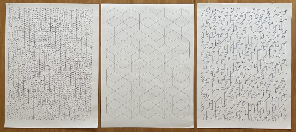
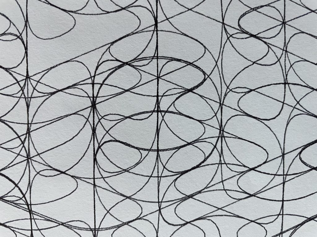
I did have some issues, especially when drawing near the bottom of the page and when drawing curves consisting of many smaller lines. These issues included:

  • I had some trouble with the pen not staying in contact with the paper near the bottom of my drawing. Sliding the belt pulleys closer to the wall and adding weight to the gondola helped with this.
  • Sometimes, the beginning of each line did not ink well due to the pen not being in constant contact with the paper. Setting the servo.dwell value to 100ms in the PenPlotter properties fixed this.
  • I found the default movement of the servo was too quick, causing the gondola to bounce when lifting the pen and the pen to slam into the paper when being lowered. To slow this down a bit, I modified the PenPlotter software to send a series of incremental servo movements rather than a single command.
  • When most pens sit still on paper, they bleed ink. To help reduce the effects of this, I minimize the pen clearance between the page and the servo when the pen is down — this minimizes the time the pen is on the paper waiting for the servo to reach its final position.
  • If there is not sufficient clearance between the lifted pen and the page, it can accidentally draw when moving from the end of one shape to the beginning of another. However, lifting it too high can unnecessarily slow the overall drawing.
  • Many short lines drawn one after another can create pen jitter. Adding weight to the gondola helps with this.
  • The plotter does not create enough downward force to use pencils (HB) and some pens (for example, Sharpie S-gel). This is somewhat mitigated by adding weight to the gondola; however, it is not feasible since more and more weight is needed the further down the page you go.

Below is another video, this one showing parts of 2 hour plot. If you’ve built a similar plotter and have tips for me, please leave them in the comments below.

Dad Finder, Map Edition

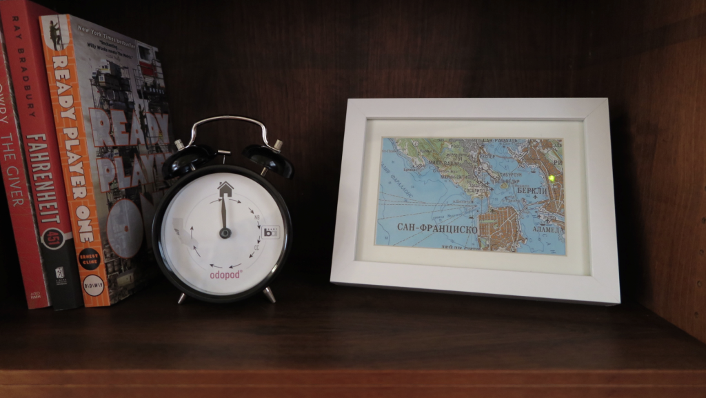
Three years after making my Dad Finder, I needed to update it to reflect my new commute. Rather than just print a new face for the clock, I decided to make a new version of Dad Finder with a new form factor and updated hardware.

I had picked up a frame from Ikea that is deep enough to conceal some hardware. I originally planned to use it to embed a few LED matrixes behind some artwork to display messages, but decided to use to mark my location on a Cold War era Soviet made map of the Bay Area.

dadfinders

Dad Finder v1(left) and v2(right)

For the hardware, I chose the Particle Photon which connects with the Paticle.io cloud platform. This was a radical simplification over the first Dad Finder which used five different components to connect to the internet and expose and API for me to hit from my mobile app. Additionally, the Particle platform has the advantage of being supported by IFTTT, so I no longer needed to use my own custom app to trigger updates as I move through different geofences.

Behind the map is a series of bi-color LEDs, one per location that I want to display on the map. On entering a geofence, I light the LED green, on exiting a geofence, I light the LED red.

The code for the Photon is available on GitHub.

Adding Sound

After using the new map for a few days, I received some complaints that it no longer made any sound. In the first version, the clock’s hand is moved by a hobby servo that makes a signature sound when moving the hand to a new position. The LEDs updated soundlessly and it turns out that my family missed having the audio cue that let them know that I was on the move.

To remedy the situation I added a small piezo speaker to the picture frame and added the ability to play melodies as the different zones are activated. We decided that some snippets from classic video games would do the trick. At present it plays the Mario 1-up sound when it starts up and either the first 4 notes or all 12 notes from the Zelda found item tune. Expanding the set of melodies so that each geofence has its own sound is on the todo list.

Using the Photon

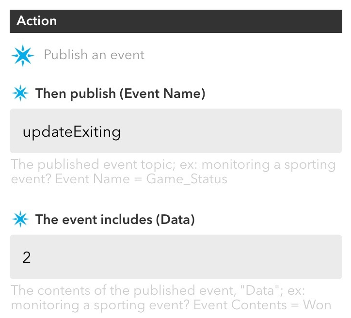
I really enjoyed working with the Particle Photon hardware. The whole platform is quite easy to use and it is nice not to have to think about connectivity at all. To pass messages between IFTTT and my Dad Finder, I subscribe two functions in my Photon code (lines 9 and 10 in the source code). To trigger the function, I set up a series of recipes in IFTTT each defines a geofence and publishes to either the updateExisting or updateEntering event with Data that identifies the correct LED to light within the data of the event.

ifttt

Screen capture of example recipe from IFTTT

These events automatically trigger the assigned functions within the Photon code (lines 33 and 40 of the source code).

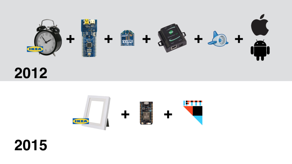
This is radically more simple than working with the Xbee radio which required coding and configuring many more pieces including the Arduino board, the radio module, the hub, the Digi cloud service and an App Engine app to trigger the events reported from my mobile app. What took many weekends to set up on version 1 of Dad Finder took only a couple hours for version 2.

Screen Shot 2015-10-17 at 2.49.49 PM

The components used to connect v1 (top) and v2 (bottom)

However, it did take a bit of time and trial and error to get things stable on the Photon. Originally I was trying to use an LED matrix and backpack from Adafruit, but using that in combination with the cloud platform seemed too much for the Photon. I found myself restarting the board often to reestablish connectivity with the cloud. Even after simplifying the code to its present state, I have had to update the firmware to improve reliability.

The Xbee system may be more complex to set up, but I don’t recall touching the code or the hardware in the three years it was running. Time will tell if the final build of v2 will be as reliable.

Transforming Sphere Lamp

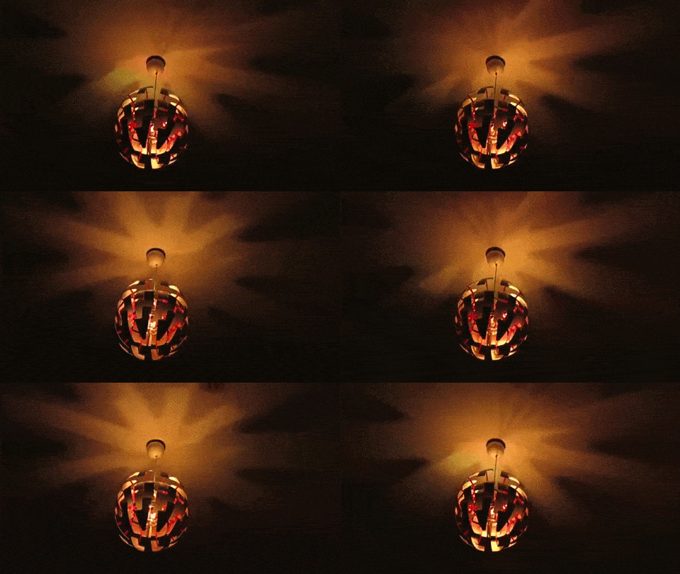
The Death Star inspired IKEA PS 2014 Pendant Lamp is a great platform for a connected home hack. Mine is shown in the video below.

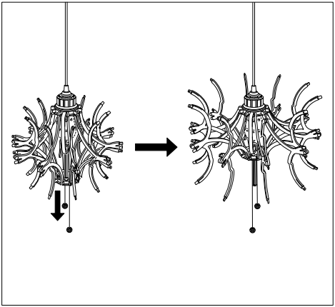
Out of the box, the lamp uses a string and pulley system to open and close the spherical shell. It is a relatively simple mechanism where two strings pull a platform up and down a central spine. Ten scissoring arms attach to this moving platform and to a fixed platform near the top of the lamp. Moving the bottom platform up the spine spreads the outer ends of the arms, opening the lamp’s outer shell (see diagram below from the lamp’s assembly manual).

open_close

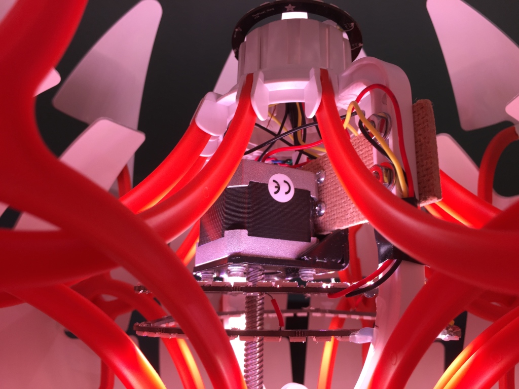
There is a void where the lightbulb normally sits between the top-most position of the moving platform and the upper platform. This provides the space for the stepper motor and LEDs needed for my modifications. The upper portion of the spine which splits in two to accommodates this space also offers a convenient platform to attach these new bits to.

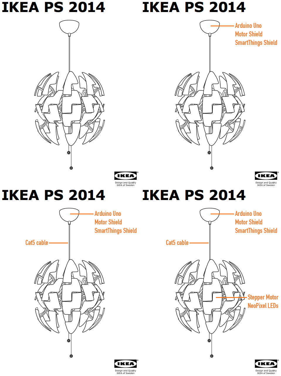
Lastly, there is cap used to cover the wiring where the lamp anchors to the ceiling. This provides a convenient space for electronics. In my case, I’m using an Arduino Uno, an Arduino Motor Shield and a SmartThings Shield.

I replaced the standard wiring with a Cat5 ethernet cable to connect my electronics in that cap to the motor and LEDs in the body of the lamp. Four of the Cat5 wires are used to control the motor and three for the LEDs, leaving one unused wire.

bits

Stepper Motor

Given the design of the lamp, it seemed easier to directly drive the lamp’s lower platform rather than try to pull the strings that the lamp ships with. I first thought I would attach a threaded rod to a standard stepper motor, but then I found this motor with a lead screw that is long enough to cover the entire length of the lamp’s spine.

I attached the motor using a standard mounting plate and a fiberboard bridge attached to the central spine of the lamp.

sphere lamp inside

Driving the motor was simple once I found a motor shield that could power it. I first tried Adafruit’s Motor Shield, but it does not provide enough power. After realizing this, I did a bit more research and determined that the Arduino Motor Shield should be able to drive the motor. And it is.

The video above shows the motor moving the platform and opening two of the ten arms. When the lamp was finally assembled, I cut off the last few inches of the screw so that it was just a little longer than the spine.

NeoPixel LEDs

For the lights, I wanted the flexibility to individually control an array of RGB LEDs. I’ve used the NeoPixel rings before in another project and really like how simple they are to use and how the ring format provides very nice visual effects with relatively simple animations.

Given the design of the lamp and the need to work around the motor’s position, I wanted to use the larger 60 LED ring configuration. Unfortunately, the rings could not fit in any one location when the lamp’s arms were both extended and contracted. Luckily, each 60 LED rings is actually made of four 1/4 circle arcs. I ended up using two sets of three arcs in triangular configurations (one triangle facing down and one facing up).

I then added a 24 LED ring to the top of the lamp to add a bit more brightness. This also works to fill some of the shadows cast on the ceiling by the internal LEDs. The results are great, especially when the lights are animating.

animate

SmartThings

I’m using the SmartThings platform to control the lamp. I went this route for two reasons: it is relatively easy to build a controller UI to use within the SmartThings app and I can integrate it with other things in my house connected to the SmartThings platform.

I created the UI by writing a device handler. The handler sends commands as strings to the SmartThings Shield which are then passed as a parameter to a designated handler function running on the Arduino.

I have not yet connected the lamp to other things but this can be done by writing a SmartThings app.

Memory

Very early on in the project, it was clear that constrained RAM on the Uno would be an issue. The first indication was that the board kept restarting with all three components integrated (while any two components worked well).

The first step was to do some simple optimizations to the types of variables I use (e.g. uint8_t in place of int). With this I was able to could get the three components working together; however, memory was still maxing out when I sent long strings from SmartThings. “SetColor: 255,255,0” would work but, “SetColor: 255,255,255” would cause problems. Simply shortening these to “sc:255,255,255” did the trick.

Then something quite surprising happened. The .toInt() function that I use to convert the strings to integers would periodically stop working and convert any three color values to 0,0,0 until I restarted the Arduino board.

I tracked this down to what I believe to be another memory issue, but one more complicated than simply running out of memory. Removing the motor code from the project (and freeing a good deal of memory) was not fixing the issue. On the other hand, removing some of the strings from the sketch that were used to parse the commands sent from SmartThings (freeing up very little memory) did fix this new problem.

In the end, the fix was to further shorten all command strings and to reduce the overall number of commands by consolidating related commands into individual commands with enums.

Persistance

The lamp can be turned on and off from a standard wall switch so it was important to me that I persist some of the settings while the power was off.

Retaining the position of the moving platform is most important since doing so frees me from adding sensors to know when the lamp is fully open or closed (and thus keep the motor from grinding away once it reaches one extreme or the other).

I also save the NeoPixel RGB and brightness values.

I originally planned to use an FRAM memory module but my previously mentioned memory constraints as well as some pin constraints imposed by the motor shield forced me to reconsider. I decided instead to take a shortcut and use the Arduino’s built in EEPROM memory. This is volatile memory rated for 100,000+ writes, but I’m ok with that trade-off for now.

Power

During development I powered the motor and lights through the Arduino with the lights hooked up to VIN. This worked fine as long as I dimmed the LEDs before running the motor.

However, when run at any significant brightness for moderate periods of time, the power would cut off. This is because the 114 NeoPixels pull about 3 amps at full brightness and my 2 amp power source shuts itself off before damage is done (there is a thermal switch that is thrown as it overheats). Using the recommended calculations it was clear that I should be using a dedicated power supply rated for at least 7 amps.

In the final installation, the lamp is powered by two 5V supplies. The first is a 2 amp supply used for the Arduino and motor plugged into the Arduino’s barrel jack. The second supply is a 10 amp supply connected to the LEDs using this barrel jack adapter (with the ground tied to both the LEDs and the Arduino).

Thats about it

All in all, this was a fun project and I’m pleased with the the results. It presented a number of puzzling challenges both with modifying the physical lamp and getting the different electronics working together and I learned a number of new details along the way.

You can find the Arduino and SmartThings code on GitHub.

If you have any questions let me know in the comments and I’ll do what I can to answer them. And, if this you build your own, I’d love to see it.

Getting Started with Arduino

If you are new to electronics, but want to start making things with Arduino, I recommend that you begin with an Uno and these great resources.

  1. Make’s Getting Started with Arduino book
  2. Make’s Ultimate Arduino Microcontroller Kit

The book includes a brief introduction to electricity and then dives into working with Arduino.

The kit includes many of the things you will want to play with as you read the book and includes an Uno.

Once you have a handle on the basics, you can add internet connectivity with the Arduino WiFi Shield or step up to the Yun.

The WiFi Shield can be used easily with the Uno, but it will limit the amount of memory and the IO pins available to you. The Yun avoids these limitations, but has some frustrating idiosyncrasies to it. Because of these idiosyncrasies, I don’t recommend the Yun for beginners.

Code for multi-switch posted to github

I’ve posted the code for my SmartThings multi-switch project to Github.

There you will find 3 files.

  1. smartthings_controller.ino – the Arduino code which communicated with the SmartThings cloud using the SmartThings Arduino library. I’m using an Uno.
  2. device_handler.groovy – the device handler code. This defines the device for use in the cloud and its UI in the SmartThings app. It is specific to the hardware, but not the use of the hardware.
  3. SmartApp.groovy – the SmartApp code. This defines how the device is used. In my app I tie specific hardware bits to specific device types (e.g. switch, switchLevel or musicPlayer).

Dad Finder

IMG_1100

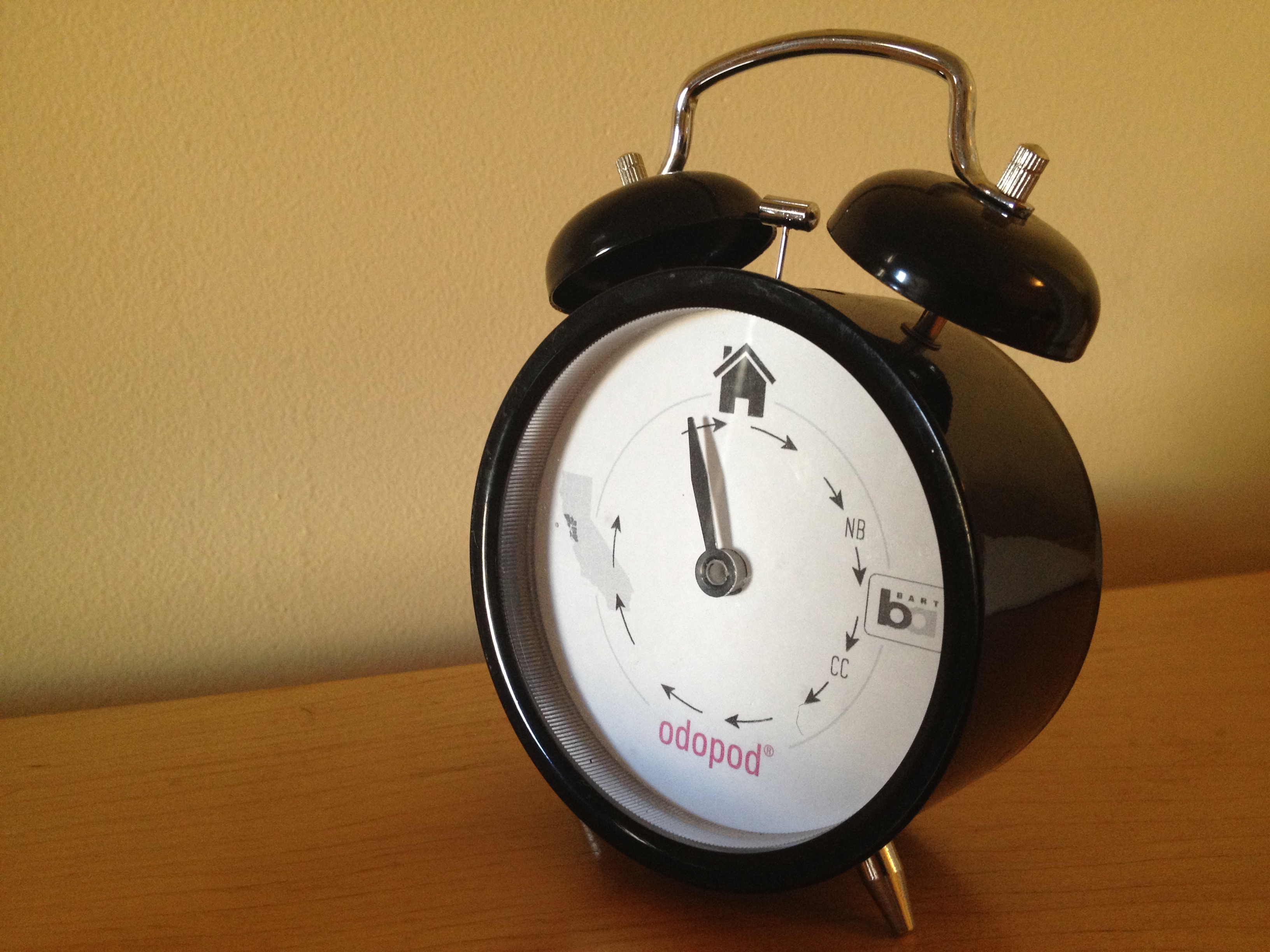
This Ikea clock was modified to display my location for my family at home. It is nice that they can check up on me without checking online. The kids are especially enjoying it.

I use 5 different geofences in an iOS app, monitoring entrances and exits for key points on my daily commute (and the bay area as a whole). The app reports the triggers to a Google App Engine app. The minimal time allowed by iOS is enough to get the call through to the server. GAE then passes the events onto the clock via the iDigi web service.

Inside the clock, I use a Fio and Xbee radio paired to my ConnectPort x2. iDigi is able to push messages through the ConnectPort to the Xbee and update my status.

Original project date: Dec, 2012.

External switch and charger for LilyPad LiPower

This Lilypad LiPower is pretty cool.

It’s basic role is to convert a 3.5v Lythium Polimer battery to 5v for Powering an Arduino micro-controller. That is done with the + and – pins in the bottom half of my photo.

Additionally it has a connection for charging the battery without disconnecting it or removing it from the project. That is done with the (partially obscured) c and – pins toward the top of my photo.

Also toward the top is a switch that turns the power to the Arduino on and off. The battery charges regardless of this switches position. This LiPower is inside the project I am working on, so I’ve added an external switch (SPST) by connecting it to two of the pins of the on-board switch.

So far this set-up is working fine. I can plug a charger externally and switch the Arduino’s power while the battery is charging or not.

UPDATE: Since writing this, I have added a connection between the B pin on the Lipower board to an analog pin on the Arduino. By doing this I can now read the voltage of the battery and light a warning LED when it gets low. I found that the Lipower outputs 5v until the battery voltage drops below about 2.9v. At that point the Lipower switches things off to protect the battery. 

Arduino, Bluetooth and Flash

Arduino, Bluetooth and Flash

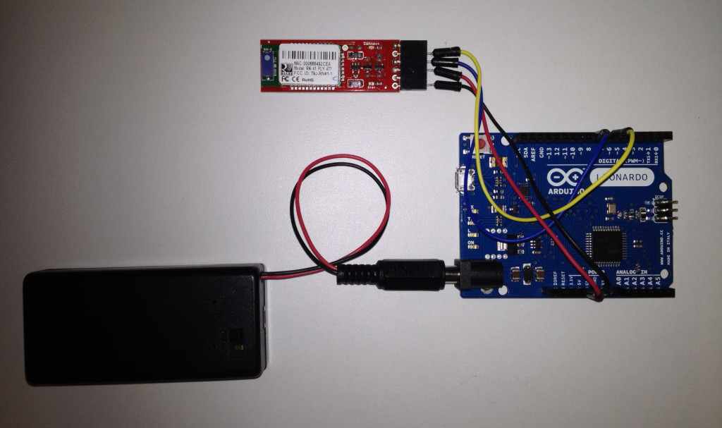
I spent more time than I would have liked trying to get a basic Bluetooth connection between my Arduino and Flash applications. At first, I could not get anything working, then I switched to SoftwareSerial and could only send data to Flash (or coolTerm). Finally, I saw the note about not all pins on the Leaonardo supporting RX and I got it all working.

I’ve posted my code on GitHub, perhaps it will save you some time. I think I have removed all my dead end trials and everything that is included is necissary for it to work.

Light Racer

light_racer

My kids love arcades where you can win tickets and buy prizes. Some of their favorite ways to win tickets are the various games with speeding lights zooming around a circle with a big button that stops the action and dispenses tickets. The ultimate goal is the jackpot light, which of course is bordered by the lowest value lights… timing is everything.

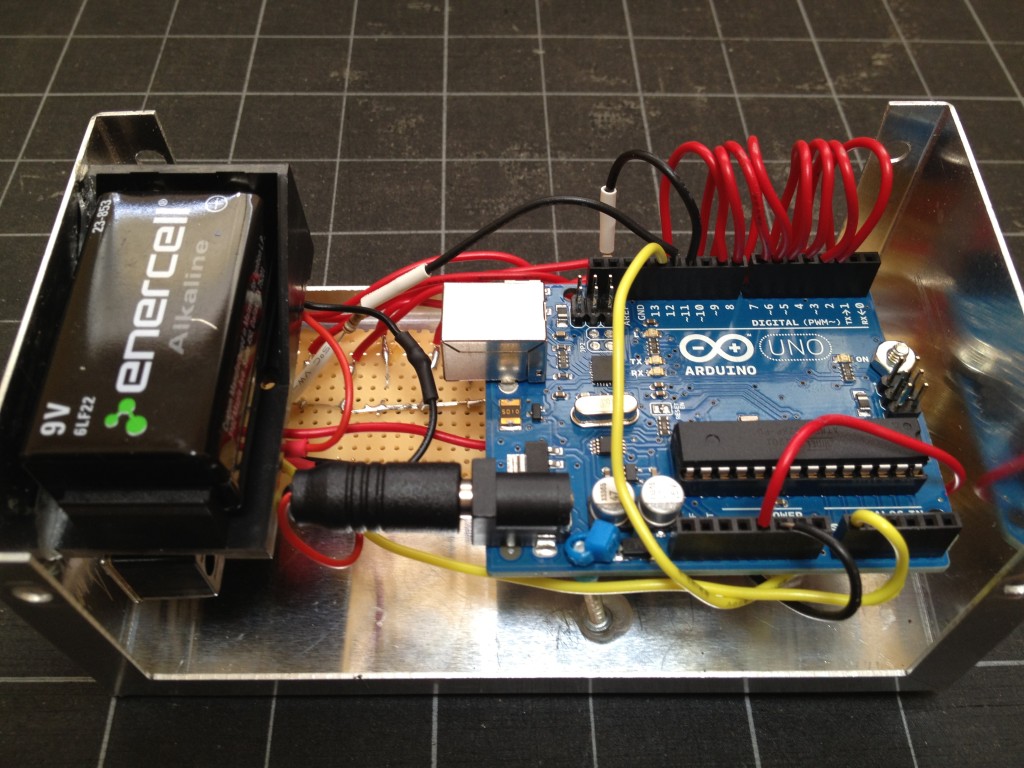
This year, as a prelude to our annual pilgrimage to the Santa Cruz Boardwalk, we designed and built training boxes. The guts (pictured above), include an Arduino Uno, 16 LEDs, a momentary switch and a 9v battery. Supporting systems include a potentiometer, assorted resistors and a very satisfying on-off switch. Everything is housed inside an aluminum project box that looks pretty good and relatively easy to work (except with is comes to anchoring anything that is not surface mounted).

Below is a video that shows the assembled boxes in action. The game has 16 different speed settings (controlled by the potentiometer) and 16 levels. Each time you stop the light on the final LED, you advance a level. If you miss that last spot three times in a row, you get knocked back a level. Finish all 16 levels and you get a fun little bonus.

Building your own toys

The kids really enjoyed designing and building their own electronic toy.

At ages 7 and 9, they are getting a good sense of what makes some of their other toys tick and are getting exposed to the benefits of iterative prototyping. Based on their feedback to the first version of the boxes, we replaced a micro pot on the inside of the box with the beefy, surface mounted knob next to the on-off switch in this version.

They also love the idea that in a couple months we can tear the whole thing down and build a different toy. We already have plans for some toys connect in a wireless mesh network for multiplayer games.